Evidence of valves not sealing as they should in the cylinder head. Also slight chamber work seems to have been carried out on this head. Abnormalities seem to be the plug recess has been blended and the shrouding around the valves also blended slightly. Almost akin to the Vizard tuning manual for Triumphs
After the disappointing rolling road dyno session I decided to look a bit deeper into the engine state. The first step was a compresion test of all 6 cylinders. Removal of the spark plugs was straightforward and the compression showed as a bit lower than expected. about 130 on a few cylinders.
This led me to believe there was either a problem with the head or the pistons/bores. The next step is to prepare the cylinder head for removal. While at this point I decsided to check and replace the cam timing chain, tensioner and gears. This will be replaced with a duplex chain and vernier cam wheel for accurate timing.
Also the cam followers. Due to wear on the rocker tips and a bit much play on the rockers and the rocker shaft; I have also decided to replace the shaft and rockers with a new shaft. This will also have new bronze bushed rockers fitted with spacers replacing the springs between rockers.
Brief procedure for Triumph top end removal.
1: Release throttle and choke cables.
2: Disconnect Remove Air filter, carbs,
3: Disconnect radiator hoses and inlet manifold hoses
3: Remove inlet and exhaust manifolds
4: Remove radiator/ fan and water pump.
5: Remove rocker cover by releasing 2 securing bolts on the top
6: Remove the rocker arm assembly by removing the 6 bolts securing the 6 pillars. Then lift off the shaft assy.
inspect the rocker tips for wear and the push rod tips and adjusters.
7: Remove cylinder head securing nuts and lift of the cylinder head.
8: Inspect the bores and head mating surfaces for wear and distortion.
New parts used
Stainless steel valves x 12
valve guides x12
payen head gasket and others associated with job
Cam followers x 12
Vernier Duplex timing kit
Rocker shaft and bronze bushed rockers x 12
Solid rocker spacers
Oil filter and Oil
Anti freeze
Duplex vernier cam gear for the for a GT6, TR6, Triumph 2000New Rocker shaft and bronze bushed rockers for a GT6, TR6, Triumph 2000New cam followers x 12 for the for a GT6, TR6, Triumph 2000New valves fitted after ne guides , skim and seat cut for for a GT6, TR6, Triumph 2000Triumph 6 cylinder head after a fresh skimNew valves installed
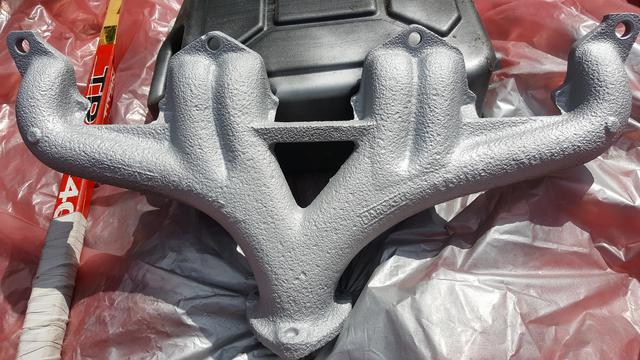
Head removed and prep work for the top end rebuild of a Triumph 6 cylinder engineAt this point I removed the valves and pressed out the valve guides. After removing the 12 valves I found evidence of gas passing past most exhaust valves. This can be seen by the blackening and pitting on the valves and valve seat face.Sandblasted water pump and housing for triumph GT6, 2000, 2500 and TR6Triumph GT6, 2000, 2500 and TR6 inlet manifold opened up (ported) slightly for better breathing to cylinder 5Triumph GT6, 2000, 2500 and TR6 inlet manifold opened up (ported) slightly for better breathing to cylinder 2Triumph GT6, 2000 TR6, or 2500 Valve clearances set. 0.25mm or 0.010″new rocker shaft with bushed rockers and solid spacer kittriumph sandblasted and painted GT6, TR6, 2000 or even 2500 exhaust manifoldtriumph 6 cylinder GT6, 2000 or TG6 duplex vernier can timing using the overlap method on cylinder 6, hence cylinder 1 on compression stroke
Cylinders 2, 3 and 4 were also passing gasses between each other, as could be seen by the blackened block face; under the gasket and gasket damage at the cylinder wall points
At this point I pressed in new valve guides and sent the head for a surface skim and valve seat re-cut.
While the head was away for the engineering work I cleaned up the head casting with brake cleaner and a scotch-brite scourer. as pictured above.
At the weekend I fitted my new 123 tune distributor. I fitted a new fusebox and relays to improve the power feed to try and eliminate any losses in the ols switchgear and corroded connections.
The fitting was very straight forward as described in the manual. The only fiddly bit was a modification I had to make to the old Delco securing clamp. This was expected as the 123 is designed to be a direct replacement for the Lucas, not really for the delco.
The modification only involved opening the clamp hole up by about 10mm in diameter. (where the clamp clamps around the dizzy.)
ignition advance curve for 123 tune fitted to A Triumph GT6 Mk3
The keener eyed folk will notice the timing is set to 0Deg BTDC until 500rpm. This is a very big advantage with starting. in the past unacheivable with classic mechanical dizzys
the button below will take you to the .xml code for you to use and modify as you need. I hope it helps.
This was a snippet from my first drive after winter. I did some debugging with regards to the ignition timing and balanced the carbs up. She ran like a dream all day.
The initial GT6 Mk3 engine start up. I did start the car when I first bought it. the only reason was to get a gauge on how it ran and if the gearbox was fully functional. The engine ran well enough considering it had not been run in 10 years.
the video shows the engine running after fitting a full carburettor service kit and all new ignition components.
The only part of the GT6 that I left relatively untouched was the engine ,gearbox and overdrive. The reason for this was I had the car Started and moving around a small yard before all the rebuild work took place. Alas after only a few miles of driving, the clutch thrust bearing started to make noises that resembled a small cage of birds.
since the car has been put away for the up-coming winter months I thought it would be a good time to undertake the necessary work.
There are a few ways this can be done. The first is to remove the engine and Gearbox as one unit. Then remove the GT6 gearbox from the 2 litre Straight six engine. Change the clutch and rebuilt in reverse sequence. I decided to go the other route and remove the gearbox from within the GT6 cabin, while leaving the engine in place.
Here is a list of Parts, tools and instructions on how to achieve this.
Parts
Clutch plate,
Clutch cover,
Thrust bearing,
If worn, Bearing carrier and actuation arm. Check for wear at the point that the arm engages the carrier ring
Gearbox Oil, ( EP90 for topping up. EP75w-80 or EP75w-90 for filling from empty.)
List of tools
Ideally 2 people
Trolley Jack,
Axel stands,
1/2″ Spanners,
7/16″ Spanners,
9/16″ Spanners,
Socket set to fit above sized
clutch alignment tool
Removal instructions
Disconnect battery (Important)
Remove passenger side glove box.
Remove gearbox tunnel carpet.
Remove gearbox tunnel
Passenger seat removal is optional. be careful not to scrape or damage it if left in.
Exposed GT6 gearbox
Disconnect propshaft. (4 x 9/16″ bolts, nuts) this may require rocking the GT6 forwards and backwards to gain access to all bolts from the cabin area.
Disconnect speedometer drive cable.
Disconnect reverse switch and overdrive unit wiring (If fitted) see picture below.
Remove the Clutch slave cylinder and actuation pin, that is located in the cabin on the bell housing by releasing the 2 1/2″ bolts
Jack up the front of the GT6, and rest securely on axle stands Chock the rear wheels to prevent the car from rolling. (Important)
remove the jack, and place under the rear of engine with a substantial block to support the engine weight.
Raise the jack to take the weight of engine and gearbox. (not lift, just support)
Remove the engine starter motor, 2 x 9/16″ bolts
Remove the gearbox / chassis mounts in the cabin, they are located on the underside of the box, and to the rear. 2 x 1/2″ bolts
Now begin removing bell housing bolts. Start from the bottom, as this will leave the top 3 studs still supporting the weight of the gearbox. 1/2″ nuts and bolts. Note: two people make this job a lot easier. 1 on the engine side with a 1/2″ spanner and 1 on the cabin side with 1/2″ ratchet driver. (See pic)
GT6 clutch bell housing bolts
Once all but the top 3 nuts, on studs have been removed, remove the 2 nuts either side of the central stud/nut. clear the engine earth strap out of the way.
Now slowly undo the top nut on the stud. As it is undone you might find the gear box slowly start to pull away from the engine plate. Just support the rear of the gearbox.
Once the nut if fully off, I would recommend one person in each foot well. hold the rear of the gearbox, pull and wiggle slightly until the gearbox bell housing has pulled away from the engine block.
We found it easiest to lift the prop shaft end of the gearbox, and rotate it into the passenger side foot well. Some jiggling was required to clear the bell housing front under the lower dash rails.
Once the gearbox is clear you will be faced with 6 1/2″ bolts around the edge of the pressure plate. gradually undo these in a criss cross pattern to prevent distortion on any mating surfaces.
Now take your new clutch plate and alignment toot and offer it up to the flywheel. Make sure the plate is the correct way round. “flywheel side” is written on the side that mates with the flywheel.
Now offer up the new clutch cover. this should locate on the 3 dowel pins next to 3 of the 6 securing bolts.
screw in the 6 securing bolts by hand until starting to apply pressure on the cover plate. Then proceed to tighten them gradually in a criss cross manner. Again, this will prevent distortion of the new cover plate. the result should look like this,
While the gearbox is removed, it is always worth replacing the clutch thrust bearing. this sits in the bell housing on a carrier, Just slide the carrier of the main shaft. carefully drift the carrier off the thrust bearing. fit the new bearing to the carrier by drifting of using a vice/press. Note: never drift bearing on the outer race. this will damage the internals and undo the good work you are undertaking
The reassembly procedure is the reverse of removal
Amendment
It must be said, (as pointed out bellow) This is a convenient time to check / replace the gearbox oil. Either when the tunnel has been lifted out, when the gearbox has been removed or just re fitted. Advisory: Try to ensure when checking the fluid levels that the car/ gearbox are sat as level as possible to ensure the fill plug drains the oil at the right level, weather in car or on the bench. I would recommend EP90 for topping up. EP75w-80 or EP75w-90 for filling from empty. The fill/level indicator plug is located on the right ride of the gearbox and is removed using a 1/2″ spanner on its square head. Fill slowly until you start to get some run-off coming from the fill hole. Leave the unit to stand for a few minutes thenreplace the square headed plug.
The old front GT6 suspensionWhen I first got the car ready for it’s MOT, I uprated the rear suspension. the read had a new leaf spring, lowering block and new Gaz adjustable shock absorbers fitted.
Unfortunately, I didn’t have the funds to set the front end up to a similar spec, although, all the springs and shocks were renewed. The were as standard. I think it has come to the time to try and match the front to the rear, to try and improve the general road holding. I have purchased a new set of uprated springs and fully adjustable Gaz shock. they were fitted last weekend.
Due to the lowering of the front end, the cambers are all shot to hell. The original way of setting these was with shims that slide behind the wishbone mounts were they meet the chassis. I think I will replace the shims with a fully adjustable top wishbone as can be seen on the Canley Classics product list.
The triumph GT6 featured on the website will soon be offered for sale. This GT6 offered for sale was purchased in 2008 and has had many thousands of pounds spent to bring it up to a very high standard. Below is a list of parts about to be fitted and also a list of parts that have been replaced. This car has only covered a few hundred miles since being put back on the road in the year 2012. If you are interested please make contact through the members login page, and I will contact you promptly.
Here is the list of replaced parts to date. All purchased new from Canley and Rimmer Bro’s
Chassis, suspension and brakes
Rear Suspension
New rear Uprated Spring.
Rear shock absorbers Gaz Adjustable.
Rear Lowering Spacer.
Rear Suspension Bolt kit.
Rubber Diff Mounts x 4.
Canley Classics Rotoflex conversion to CV Driveshafts £500.00.
Rear Suspension bushes Complete.
Front Suspension
Gaz fully adjustable Front shock absorbers (height / damping).
Uprated front Suspension springs x 2 Canley Classics Camber adjustable front wishbones Rose jointed Anti roll bar drop links Track rod ends. All Suspension bushes x 8.
New Uprated anti roll bar.
Complete front Suspension Bolt kit.
Brakes
brake Master cylinder
brake drums x 2. Brake shoes. Brake spring kit. Hand Brake cable.
Solid brake Lines.
Goodridge Braided Brake Lines x 4.
Brake drums x 2.
Brake shoes.
Brake spring kit.
Hand Brake cable.
Front Brake Disks x 2.
Other machanicals
Prop Shaft UJ,s x 2.
Engine Mounts x 4.
Steering Rack.
Uprated, Rack-column link.
Hub pivot ball joints x 2.
Front Wheel Bearings x 4.
front hub steering trunnions x 2.
Body Panels
Front Outer Wheel Arches
Rear Wings x 2
rear Outer Wheel Arches
Outer Sills x 2
Inner Sills x 2
Sill Strengtheners x 2
Sill filler Panel x 2
Sill End cap x 2
Floor Pans x 2
Cross members x 2
Boot Floor
Rear valance
Rear Light panel
A-post panel x 2
Trim and other parts
Roof lining
Black carpet
Walnut Dashboard
Dial chrome bezels, glass and seals Windscreen Windscreen seal and trim Windscreen wipers
Windscreen wiper mount bevels, seals and nuts
Windscreen motor mount Strap and base Rear Screen seal and trim (trim not fitted) Boot lid Seal Door hinge Bolts and gasket. Door Slam plates. Door cards. Rear ¼ panels. Door weather seals, interior/exterior. Rear 1/4 Light window seal. Carpet Set. Gearbox Tunnel. Rear light Seals. Rear Light Bulb holders. Rear chrome horse shoe trim. Wing mirrors x 2
Electrical
Starter Solenoid.
Wiper Motor.
All new Bulbs.
Bulb Holders.
New Coil.
Electronic ignition kit.
New HT leads.
New HT cap
Fluid Control
Fuel line, Complete tank to Carbs.
Fuel tank Sender Seal and locking ring.
Full Stromberg Carb refurbishment kit x2.
Fuel pump.
New cooling / heating hose set.
Refurbished radiator (sender mounting boss soldered for cooling upgrade if required)
New water pump.
Heater control valve
many thanks to Heather and her staff at James Auto,s. They were very Quick, professional, and helpful with regards to my MOT. Heather replaced a few bulbs on the car at no charge to ensure the car was up to scratch in all areas to earn it an MOT
Here i am fitting the front panels and bumper to my Triumph GT6 Mk3. Unfortunately i have had to fit an old bumper for now.
In these picture I am trial fitting the front valance so I can line up some brackets to be welded on. These will be the mounting points for the front numberplate.
The front indicators are installed and working after a few hours tracking faults in the loom. Hazard light were a pain. I got there in the end after finding the green/red and Green/white wires from the switch to the bulbs had internal breaks in the loom.
I am trying to get the car ready to move to another location. Ideally I would like to have the valance painted and on. Also with the bonnet fitted and aligned. The difficulty is in getting the bonnet to the car. I might resort to putting it on a roof rack.
Gt6 MK3 rear end view as the car starts to come togetherGT6 MK3 bonnet fitted
The GT6 Information, Restoration,and Documentation Site.